For past few months I am working on a project based around Meadow platform that allows .NET programming for IoT. Greatest thing about it – it is programmable using full .NET Standard, so almost any .NET developer can easily just gram one, learn some platform specific basics and start being productive very soon, even without prior IoT experience. It’s extremely easy to write (assuming you know C# of course) and allows usage of most .NET goodies you might want – events, threads, asynchronous programming? LINQ? Networking? Whatever you might want – if you can do it in console app you probably can do it here to!
Obviously there is also a lot of specific stuff too. There must be classes for example to control hardware – but in principal they work as usual .NET stuff, and there is a lot of APIs for different devices already in Meadow Foundation. But what to do if you bought device and there is no driver for it yet?
What is Meadow?
At the moment we have Meadow F7 board available, that has STM32F7 and ESP32 chips on it and multiple General Purpose Input/Output pins. It also supports multitude of different communication protocols with other devices, like UART, SPI, I2C, PWM, also wireless communication using WiFi or Bluetooth etc. For more details about Meadow and all the possibilities I encourage everyone to just check Wildesness Labs’s website, as just presenting everything briefly would take whole post. In very short – it’s development board allowing to control multiple peripherals that, contrary to popular Arduino boards for example, can be completely programmed using C# and .NET.
What does it give us? For me personally – I was always too lazy to learn C-like programming of Arduino. But here – I just can use everything I already knew (and have opportunity ot learn more!) from PC programming and quickly translate my ideas into working device. For most “inner” things we can just program it as any console application. You want to run multiple threads, each doing something else concurrently plus be able to respond to multiple different Events? If you know how to od it on PC – you know how to do it here too! The only unusual things start when we get to contacting peripherals.
Let’s say you want to make simple room temperature monitor. You make a thread that periodically reads temperature sensors, so it won’t block main thread. If temperature threshold is exceeded you may want it to invoke Event, that will “inform” subscribing objects like the updating display, working on another thread, to show warning message, another subscriber might be AC control that will start heating/cooling room etc., at the same time you might want to have thread awaiting messages over network coming from either user input in control application on other device, or Cloud service, could also be sending data to them, etc. possibilities are endless. And, as before – almost all of that code will be exactly the same as if you’d be programing this for PC. Only difference will be when contacting devices, but it’s all abstracted in user friendly form. For example getting temperature from sensor might be as complicated as calling float temp = sensor.Temperature; and that’s all – now you’ve got float containing temperature and you can work with it like any other float in whole .NET!
But if you don’t have specific driver – don’t despair! It might be a bit trickier – but still if you get your head around it – it will become quite easy!
I2C
As mentioned above there are multiple different protocols that can be used to communicate with devices, but this time I want to focus on one I’m using the most in my project and also the one that at first glance can seem quite complicated. What is I2C?
I2C (Inter-Integrated Circuit), pronounced I-squared-C, is a synchronous, multi-master, multi-slave, packet switched, single-ended, serial communication bus
https://en.wikipedia.org/wiki/I%C2%B2C
That’s what Wikipedia says. If you’re interested in bare-to-the-metal details this article provides extremely deep info, also most datasheets of I2C based devices provide deep explanation of inner workings of it. But what does it mean in practice, if you want to just use it?
In short – it’s a master – slave bus, where our Meadow board will be master controlling one or multiple slave devices connected to it. It’s a bus so there can easily be connected multiple separate devices (in my current project I’m controlling around 10 different modules from one bus), that just need to have unique addresses. There are also some electrical limitations, like maximum voltage on “off” or 0 signal, that can rise due to too many pull up resistors, or maximum capacitance of a bus – but for this post let’s keep it to programming, assuming for now you have one or only few devices tops.
Each device has registers – small memory cells that can hold usually one or two bytes of data. Each one of them can be Read only or Read and Write. In short – to control device you send first it’s bus address (7 bit number – between 0 and 127) and then read or write command to specific register. If you want for example to reset device to factory state – you must just find which bit of which register contains RST bit and then write to that register data containing 1 on specified position. Device seeing 1 on reset bit – will reset it’s configuration. Or, if you want to configure it – you just need to write correct data into respective register. On the other hand, if you want to get some data from device – you just read contents of correct register.
Does it seem complicated? Probably. Is it hard? All the addresses, registers, bytes and bits…
But here comes the whole beauty of what Wilderness Labs did – all of this is abstracted using I2cPeripheral class! You don’t need to know how to compose correct message, where to put read or write bits, where to put address, how to send it – you just instantiate object passing just correct configuration – bus speed (usually 100kHz, 400kHz or 1MHz), device address that you got from datasheet (and that can sometimes be changes physically on board, more on that later) etc. and now you have an object that you can just easily invoke simple Read or Write commands, and all lower level stuff is done for you! But let’s just see it on example.
Programing INA219 driver
For this example I’ll be using INA219 voltage and current sensor that I had to program myself some time ago but it will be very similar for any other device. It’s extremely useful – it measures voltage on both sides of shunt resistor that is in series with measured circuit, from that difference it calculates voltage drop on it and knowing it’s resistance it can calculate current in the circuit. And knowing voltage and current – getting power is just multiplying them. Let’s see how to get it working!
The whole code I’ll be referring to you can check here on my GitHub.
Unless we’re porting driver from some other platform like Arduino (which I haven’t done yet) fist step is getting datasheet. As we can see in attached it contains all technical details about chip, even much more than we need.
Just a note – datasheets usually contain information about pure microcontroller, while usually we’ll be working with ready to use modules based around them – containing also all other electronic components needed for it to work. From practical perspective it means some things might be module specific. For example take a look at those two modules:
They are both based on INA219 chip, one produced by DFRobot, second by Adafruit. Are they the same? Not exactly!
Biggest difference? DFRobot has microswitch to set bus address, that can be easily switched, Adafruit one has solder pads requiring to bridge them to change address. Both allow to change two bits. For both of them manufacturers specify default address as 0x40 in hexadecimal, so 64 in decimal, with possibilities for 3 other addresses. What datasheet says about address then? On page 14 we have all possible addresses listed – and it’s muuuch more than 4! That’s why it’s important to refer not only to chips datasheet but also module.
Ok, for now let’s assume we’re keeping the default address of 0x40, that is 01000000 in binary. Let’s start coding!
First I created separate class for it, called… Ina219. Inside it main object I will need is mentioned above I2cPeripheral – this will allow communication with module. To instantiate it we need I2cBus object representing physical I2C bus (I’m using it through II2cBus interface) – for now let’s just assume we will get it later, and byte containing address, I added also INA219Configuration object to be able to configure it at startup.
public INA219(II2cBus bus, byte address = 0x40, INA219Configuration config = null)
{
    ina219 = new I2cPeripheral(bus, address);
    if (config == null) configuration = new INA219Configuration();
    else
    {
        configuration = config;
        Configure();
    }
}
As you can see config object is optional, if not passed I will just use default configuration. So what exactly is this configuration?
Now as we have I2cPeripheral we can start interacting with module. Let’s take a look at registers first to know what to do. Let’s take a look at page 16 of datasheet:
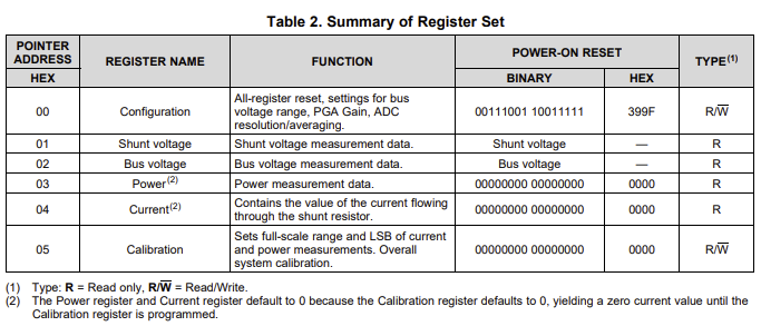
As we can see it is not that complicated. We have just 6 registers, 2 bytes long each, each name is quite self-explanatory. If we want to get measured current – we read register no 04 and we get value containing that info. If we want to configure it – we write appropriate data to register 00. As 2 bytes is 16 bits each of this operations we can easily perform by calling ina219.ReadUShort() or ina219.WriteUShort(). Both of those methods take register address and optional byte order parameter plus data in case of writing. Register address – it’s just the number from table above. Byte order depends on device, in case of INA219 we need to use BigEndian from enum ByteOrder which informs underlying method that it the most significant byte will be first and least significant one last. For example to send number 32000, that is 01111101 00000000 in binary, we need to send it that way, while Little Endian architectures might require reverse order 00000000 01111101. Fortunately this is just something you need to get – again – from datasheet (page 14, 8.5.5.2 Serial Interface – “All data bytes are transmitted most significant byte first.” and then Meadow is taking care of it all if you just provide it with appropriate information.
For example to configure it I wrote Configure method with 3 overloads depending how do we provide configuration:
public void Configure(INA219Configuration configuration)
{
    this.configuration = configuration;
    Configure();
}

public void Configure()
{
    int config = 0;
    config = config | (byte)configuration.Mode;
    config = config | ((byte)configuration.ShuntADC << 3);
    config = config | ((byte)configuration.BusADC << 7);
    config = config | ((byte)configuration.Pga << 11);
    config = config | ((byte)configuration.BusVoltageRange << 13);
    ina219.WriteUShort((byte)RegisterAddresses.Configuration, (ushort)config, ByteOrder.BigEndian);
}

public void Configure(ushort config)
{
    ina219.WriteUShort((byte)RegisterAddresses.Configuration, (ushort)config, ByteOrder.BigEndian);
}
Third overload shouldn’t be used, as it doesn’t keep track of current configuration in the INA219 object, so it might be different in object than in chip itself. But it is also easiest to understand showing all simplicity here.
- We take ushort containing 16 bits, same as register size,
- We take register address from enum containing them for simplicity (although could be just plain number, using enums it’s just easier without the need to check in datasheet if you forget),
- We take enum
ByteOrder.BigEndianas explained above, - And we put them in ina219.WriteUShort(). Magic done, our Ina is just configured! But how to get configuration ushort?
First overload is the one that should be used most, as it’s storing configuration object in INA219 instance, allowing to keep track of how it is set. After that it calls second overload which takes configuration stored, translates it into appropriate 2 bytes and then writes to device. Using those two methods assures that we never have difference between values stored in object and chip, separating into two allows to call Configure with new configuration, or in case of constructor, which assigns configuration object directly, can transmit it without unnecessary call to first overload.
Let’s try to understand configuration. First we, of course, check datasheet, page 19:

As we can see those 16 bits contain different settings but we need to send them all at once, so even if we want to change one setting we need to prepare new configuration bytes and send whole thing at once. Also bit 15 is reset bit, so if we need to reset it to defaults we can just transmit any ushort containing 1 on that specific bit. How?
Bitwise operations
This is probably most complicated part of writing driver. Let’s assume first we want to send reset bit. We need to send 10000000 00000000 so decimal 32768 or, to be honest anything else as long as it starts with 1, could even be 11111111 11111111 in that case (but let’s not do it, ok?). How to get 1 on first place?
There are multiple options.
ushort msg = 0b1000000000000000;
ushort msg = 0x8000;
ushort msg = 32768;
But all of them require knowing final number to transfer. In that case of reset it’s not a problem, in others might be. So let’s say we want to have 1 at position 15 knowing only that, not using full number.
Lest start by instantiating empty ushort. then add 1 to it. And what then? We can just use bitwise operator << to move this bit over to the left by 15 positions!
ushort msg = 0; //0000 0000 0000 0000
msg += 1;       //0000 0000 0000 0001
msg << 15;      //1000 0000 0000 0000
We entered number 1, much easier to remember than 32768, and just shifted it to correct position! Now we have reset message ready to send!
Ok, what about complex messages containing different configurations?
Here we need to send 5 different values. I don’t want to explain every one of then here so if interested in details you can check datasheet. For each of those values we have multiple possibilities, so for easier use I just created enums for each of them:
private enum RegisterAddresses
{
    Configuration = 0x0,
    ShuntVoltage = 0x1,
    //(...)
    Calibration = 0x5
}

public enum ADCsettings
{
    Mode9 = 0b0000,
    Mode10 = 0b0001,
    //(...)
    Samples128 = 0b1111
}

public enum ModeSettings
{
    powerDown = 0b000,
    ShuntVoltageTriggered = 0b001,
    //(...)
    ShuntBusContinuous = 0b111
}

public enum BusVoltageRangeSettings
{
    range16v = 0,
    range32v = 1
}

public enum PGASettings
{
    Gain40mV = 0b00,
    //(...)
    Gain320mV = 0b11
}
Enums are based on setting names in datasheet to easily access them, value names also on corresponding datasheet names, and values are written in bit format straight from docs – so I don’t need to calculate hex or dec values – if datasheet says 1010 – it is 0b1010, no room for error that way!
So now having all configuration as easily readable enums instead of some strange numbers, let’s build config.
We need 5 values, so we need to take 5 parameters. I keep them as enums as long as possible for code readability, translating into numeric values only when needed. So let’s built INA219Configuration class containing all configuration:
internal class INA219Configuration
{
    BusVoltageRangeSettings busVoltageRange;
    PGASettings pga;
    ADCsettings busADC;
    ADCsettings shuntADC;
    ModeSettings mode;
    public INA219Configuration() //Constructor for default configuration
    {
        busVoltageRange = BusVoltageRangeSettings.range32v;
        //Assigning other values to defaults;
    }
    public INA219Configuration(BusVoltageRangeSettings busVoltageRange, PGASettings pga, ADCsettings busADC, ADCsettings shuntADC, ModeSettings mode)
    {
        this.busVoltageRange = busVoltageRange;
        //Assigning other values;
    }

    internal BusVoltageRangeSettings BusVoltageRange { get => busVoltageRange; set => busVoltageRange = value; }
    //other properties...
}
As you can see, if for example we want to configure operating mode to calculate mean over last 128 samples – we just select corresponding enum – ADCsettings.Samples128 – definitely MUCH easier than manually putting there 0b1111.
So let’s say we decided about configuration, we instantiated object containing all selected enums, what’s next? Let’s check Configure() method again, as it shows us all the magic there:
public void Configure()
{
    int config = 0;
    config = config | (byte)configuration.Mode;
    config = config | ((byte)configuration.ShuntADC << 3);
    config = config | ((byte)configuration.BusADC << 7);
    config = config | ((byte)configuration.Pga << 11);
    config = config | ((byte)configuration.BusVoltageRange << 13);
    ina219.WriteUShort((byte)RegisterAddresses.Configuration, (ushort)config, ByteOrder.BigEndian);
}
As before we start with ushort config = 0. That way we have empty placeholder for final message. For other lines, written here in compact form, let’s expand one line to better see what it does.
Let’s assume we want 2 samples mode, we don’t need to check datasheet as we just have enum ADCsettings.Samples2 which is even easier to write with IntelliSense prompting us correct names when only we start typing. So what does that line do?
//casting enum into byte let's us get value 00001001 from it and write it into tmp
ushort tmp = (byte)ADCsettings.Samples2 //tmp = 0000 0000 0000 1001
//we shift it to the left by 7 places, so read value is on correct position
tmp << 7; //tmp = 0000 0100 1000 0000
//and then we use bitwise OR, that performs OR on each bit of both values:
//config = 0000 0000 0000 0000
//OR
//tmp =    0000 0100 1000 0000
//result = 0000 0100 1000 0000
Now if we OR that with another configuration value, it will fit on it’s selected position as they don’t overlap and that way we can get final configuration, for example for default one (names as per datasheet, page 19):
config = 0000 0000 0000 0000
BRNG =   0010 0000 0000 0000
PG =     0001 1000 0000 0000
BADC =   0000 0001 1000 0000
SADC =   0000 0000 0001 1000
MODE =   0000 0000 0000 0111
//everything ORed
config = 0011 1001 1001 1111
We get 0011 1001 1001 1111 – which is default configuration – page 18!
Now we just write those two bytes/ushort to module as explained before, using enum RegisterAddresses.Configuration as address, which is self-explainatory enough I think, and we have it configured and ready to work!
Reading data
Ok, we now know how to write data to module, how about reading values? Let’s assume we want to check Bus voltage. We already have appropriate enum with register address, so we call:
ushort voltage = ina219.ReadUShort((byte)RegisterAddresses.BusVoltage, ByteOrder.BigEndian);It’s again quite easy – just passing enum with address, and BigEndian as required. And we’ve got bus voltage register contents in out ushort.
Unfortunately life is never that easy, but again – just need to get your head around that, check datasheet and we’ll get final, human readable value. So – to our PDF, page 23:

Ok, so what does it says?
First we see that value is shifted by 3 bits to the left. Then we see CNVR and OVF bits – for now we can ignore those. So we need to shift value by 3 bits to the left voltage >> 3
Next we need to calculate realt value in volts from it. We see that LSB=4mV. It means that change by 1 in this registers means change by 4mV in real-life values. So we can just multiply ushort value by 4mV, if we want result in full Volts we can divide result by 1000 – and we have real value!
float busVoltageLSB = 4f / 1000f; //0.004V
public float ReadBusVoltage()
{
    //for example 16.4V/0.004 = 4100 = 0001000000000100 in binary
    ushort register = ina219.ReadUShort((byte)RegisterAddresses.BusVoltage,
    ByteOrder.BigEndian); // register = 1000 0000 0010 0000
    register = (ushort)(register >> 3); // register = register = 0001 0000 0000 0100
    float voltage = register * busVoltageLSB; // voltage = 4100 * 0.004 = 16.4
    return voltage;
}
That’s it! Just a bit of basic math and carefully reading datasheet and we got our value!
Carefully reading datasheet – yep, that might be hardest part. But of you do it – you open yourself to whole world of possibilities! So it’s really worth it!
Summary
I really hope this will help someone. When I first thought about programming my own I2C drivers I was like “What? Never! It must be extremely complicated!” Fortunately thanks to all hard work by Wilderness Labs developers it is made really easy, so don’t hesitate, try yourself!
Of course INA219 has much more options than I described above – but this was not supposed to be INA219 tutorial, just general I2C one. To get other values you just do the same, based on datasheet values, to calibrate it – you calculate appropriate value based on datasheet and write to correct register etc.
If you’ve made it all the way here – thank you very much for reading! And now go out and code!
This is tremendous. I was struggling with some of the lower-level elements when looking at existing drivers and this is the *perfect* roadmap. I’m working with a sensor that has options to both send readings on request and to take a single command to provide pushes of readings at an interval. Until this article I was wondering how to instrument this. Many, many thanks!
Glad to be helpful 🙂